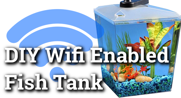
DIY Wifi Enabled Fish Tank
I recently purchased a Aquarius AQ11204 BettaView Brite Corner Tank and a cheerfully blue betta fish. The tank is a simple corner shaped tank that fits perfectly on my desk and adds a bit of life to the mountain of technology that every other inch of my office occupies. This particular tank also incorporates a multi-mode RGB LED that can cycle through different modes by pressing the button at the top. Overall, even without modifications, it’s a great tank!
But.. the lighting is a bit lacking. The light can only be toggled to stay on for a few hours after a complicated sequence of long and short button presses. The lighting modes are quite boring with only a few solid colors and an awkward attempt at PWM control of the LEDs for the fading. Now this got me thinking how I could improve this. I’ve had a bag full of ESP8266 boards for a while now, almost 6 months, that I haven’t done anything with.
For those who do not know anything about the ESP8266; it’s specs are as follows:
- Cost is less than $2 shipped!
- Wi-Fi chip with full TCP/IP stack
- 80 MHz Microcontroller
- 64 KiB of instruction RAM
- 96 KiB RAM
- External 512 KiB flash.
In short, a powerful enough WiFi enabled microcontroller to control both the IO devices and host a basic HTTP server on the cheap!
So let’s get started! The goal for this project were as followed.
- Weekend project. Shouldn’t take more than two days from start to finish.
- Monitor and record water temperature every 30 seconds.
- Text message alert if the water temperature reaches a concerning level.
- Mobile friendly web interface for changing the color and effect mode. (Constant color, fading, etc)
Parts List
The links provided below are through the Amazon Affiliate program. If you want to do this project, and don’t mind waiting for the parts, then I highly recommend buying most of them off of eBay. Buying from eBay should lower the project cost (minus the tank) to around $12 bucks!
| Name | Qty | Price | |
|---|---|---|---|
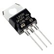 |
3.3V 950mA LD33V Voltage Regulator | x1 | $1.50 |
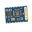 |
ESP8266 WIFI Module | x1 | $5.99 |
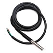 |
Waterproof Temperature Sensor DS18B20 | x1 | $5.99 |
 |
10uF Polarized Capacitor | x1 | < $0.08 |
 |
0.1uF (100nF) Capacitor | x1 | < $0.08 |
 |
5V DC Wall Power Adapter | x1 | $7.98 |
Brief Overview
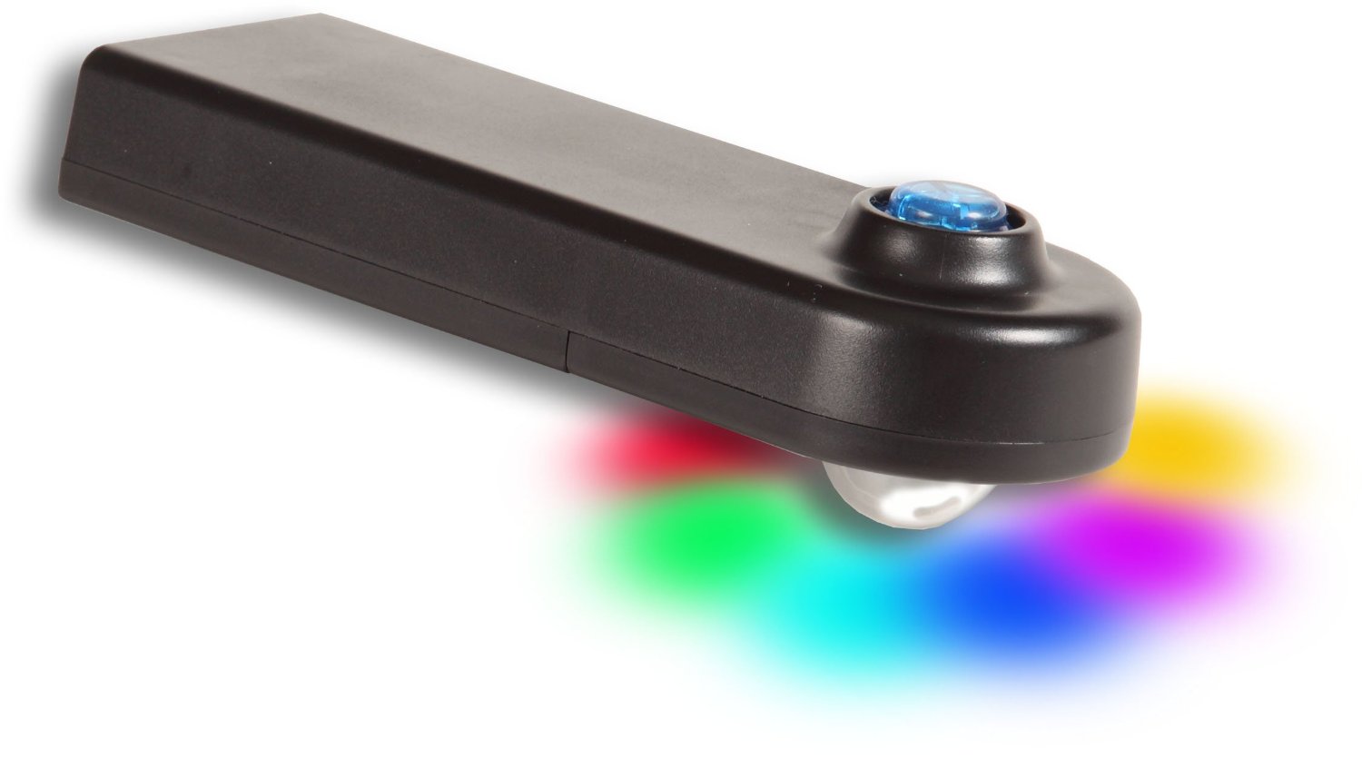 On top of the tank is a removable, oblong puck shaped module that encloses the
RGB LEDs, the big blue button for controlling the LEDs, a 5V power barrel input
port and a battery slot for 3 AAA batteries.
On top of the tank is a removable, oblong puck shaped module that encloses the
RGB LEDs, the big blue button for controlling the LEDs, a 5V power barrel input
port and a battery slot for 3 AAA batteries.
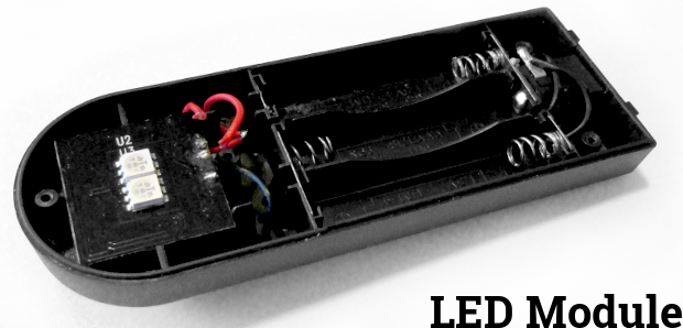
LED Module
Inside of the LED Module, for the lack of a better name, consists of a few bare components. From left to right we find the PCB, battery contacts and the 5v power connector at the rear.
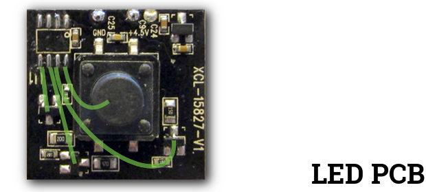
LED PCB
The LED PCB pictured above is a simple layout consisting of MCU (removed in the picture), an NPN transistor array with pull down resistors for each channel of the RGB LEDs, self-power off logic(transistor + capacitor) and power button. The MCU was not investigated due to it being unmarked and most likely being a masked ROM. In the picture I’ve highlighted the pinout from the MCU footprint for each of the RGB LED transistor leds and the button.
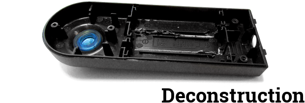
Deconstruction
Deconstruction was quite easy. Started by removing all of the components and breaking the plastic pieces of the battery separator. In the future, I hope to find the right Dremel bit for cleaning up such tasks. Not a lot of time was spent freeing up space as there’s plenty on the inside for what I wanted to do.
Schematic
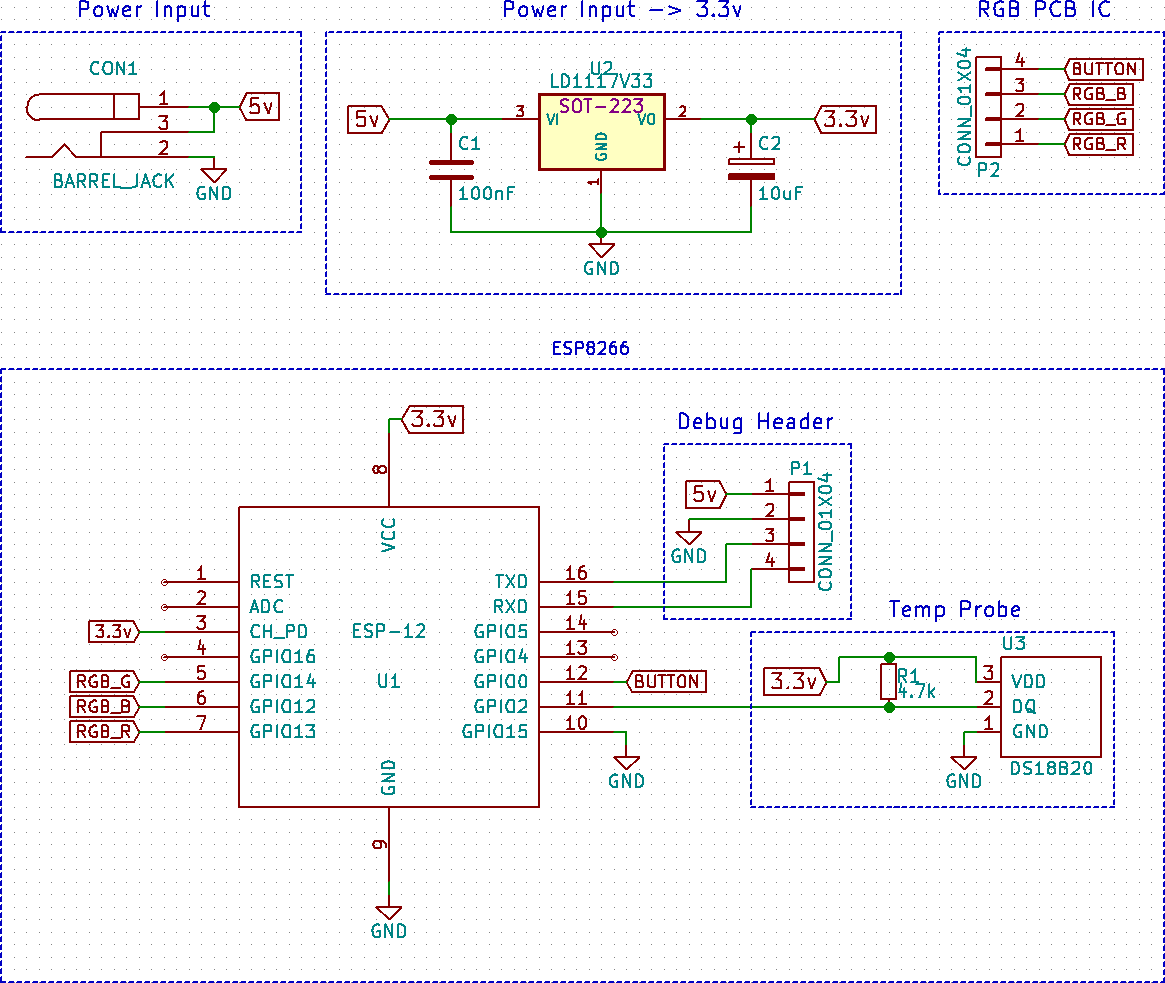
The schematic for this project is actually quite simple and is built of a couple sections. Were saving a lot time by directly controlling the transistors on the LED PCB. The LEDs, wired in parallel, would normally pull too much current for the ESP pins to handle, but in this case we should be fine since we’re only controlling the transistors directly.
Power Input - The power input is the barrel jack located on the device and provides 5v to the LED PCB and to the LD1117V33 voltage regulator.
Power Input -> 3.3v - This is the 5v to 3.3v regulator along with the associated stability capacitors. Datasheet
RGB PCB IC - This section represents 4 of the MCU/IC pins found on the PCB as described previously in the PCB LED section.
ESP8266 - In this project I’m using the ESP8266 ESP-03. CH_PD must be tied high, 3.3v, for the ESP8266 to turn on and GPIO15 must be tied to ground. (More information about the different board variations of the ESP8266 can be found here.) GPIO0, also know as PROG, must be tied to ground on power to enter programming mode.
An optional decoupling cap of 0.1uf on the VCC/GND pins may be added, but was omitted.
ESP8266 - Debug Header - In this project I used a simple 1x4 pin header to breakout a connection for the TxD, RxD, 5v, and GND. This allowed me to program and debug with a 3.3v USB serial cable that also provided 5v for the LED PCB.
ESP8266 - Temp Probe - The temperature probe is a DS18B20 and was chosen as it comes in a waterproof enclosure. The DS18B20 communicates over 1-Wire and a 4.7k pull down resistor is used on the VDD/DQ pins.
Hardware
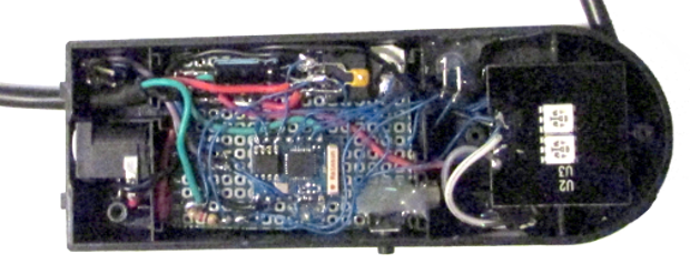
The hardware is pretty straight forward. Following the schematic along with a bit of hot glue. The connections were made on top of a piece of prototyping board. As this is a one off prototype and won’t be moving around I was not worried about using hot glue or the appearance of the internal circuitry. Yummm hot glue.
Software
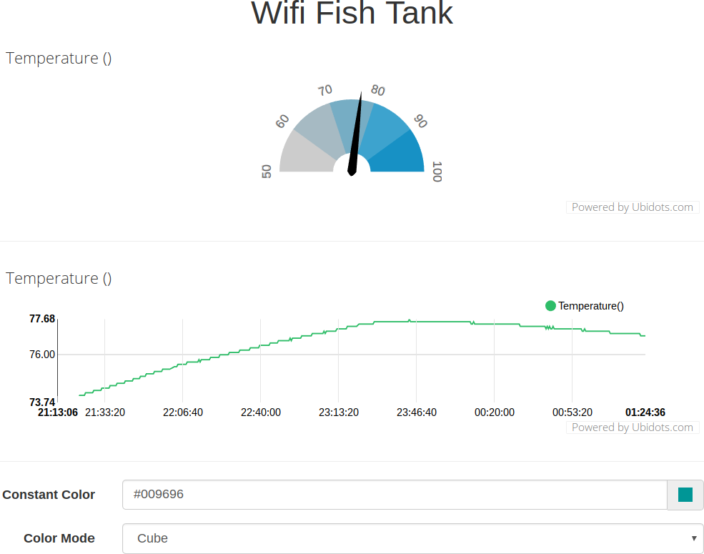
The software is easily the most interesting part of this project for myself. The project as a whole really demonstrates that the industry for IoT devices is currently possible with the low cost of the hardware required. However, in a lot of ways we lack the software needed to connect everything together. For this project, the web interface is made of simple HTML, CSS and Javascript. For a quick UI I went with Bootstrap. This provides a clean and responsive interface both for desktop and mobile.
Initially, I wanted to code this simple project using Angular or React, but was worried about packing everything up on the ESP8266’s somewhat limited 512 KiB of storage. So in the end, I went with a more traditional solution of using jQuery for the basic UI switching and GET based communication.
The C/C++ side of things was pretty straight forward as it’s using the ESP8266 library for hosting and routing the HTTP server. The build process consists of using the PlatformIO platform along with a Python script to build and compress the HTML resources into C headers. The LED functions were initially coded by myself, but later I came across “Arduino-RGBEffects”, which I found to be better structured and already had a clean cube/fade effect implemented.
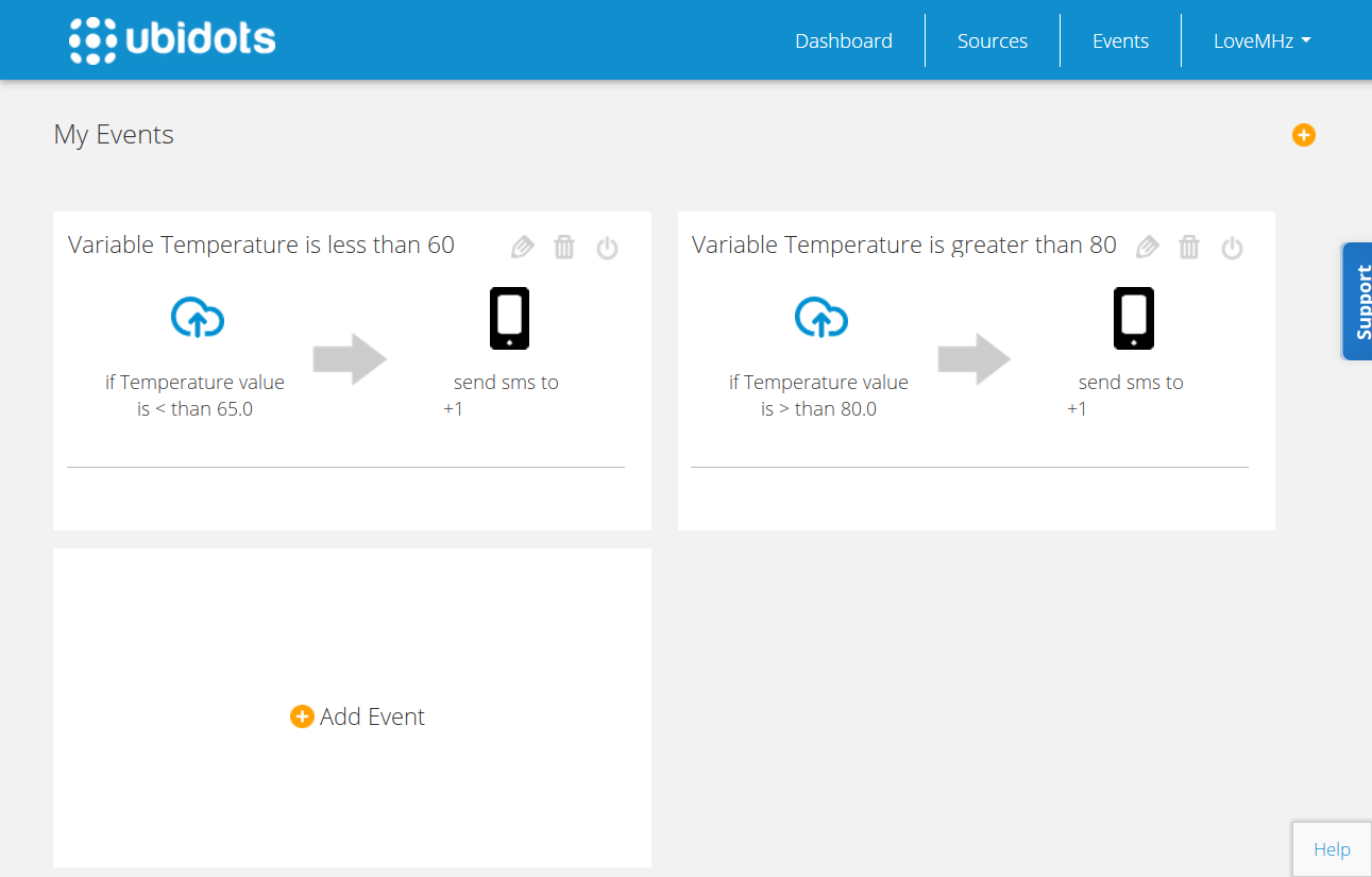
Another great feature of ubidots is the event system. This allows me to set up events for any condition based on the sensor I have installed which, in this case, was the water temperature sensor. Currently, I have a text message alert setup for, if the water temperature reaches an unsafe level of less than 65 °F or greater than 80 °F, I will be alerted via text message.
The World of IoT
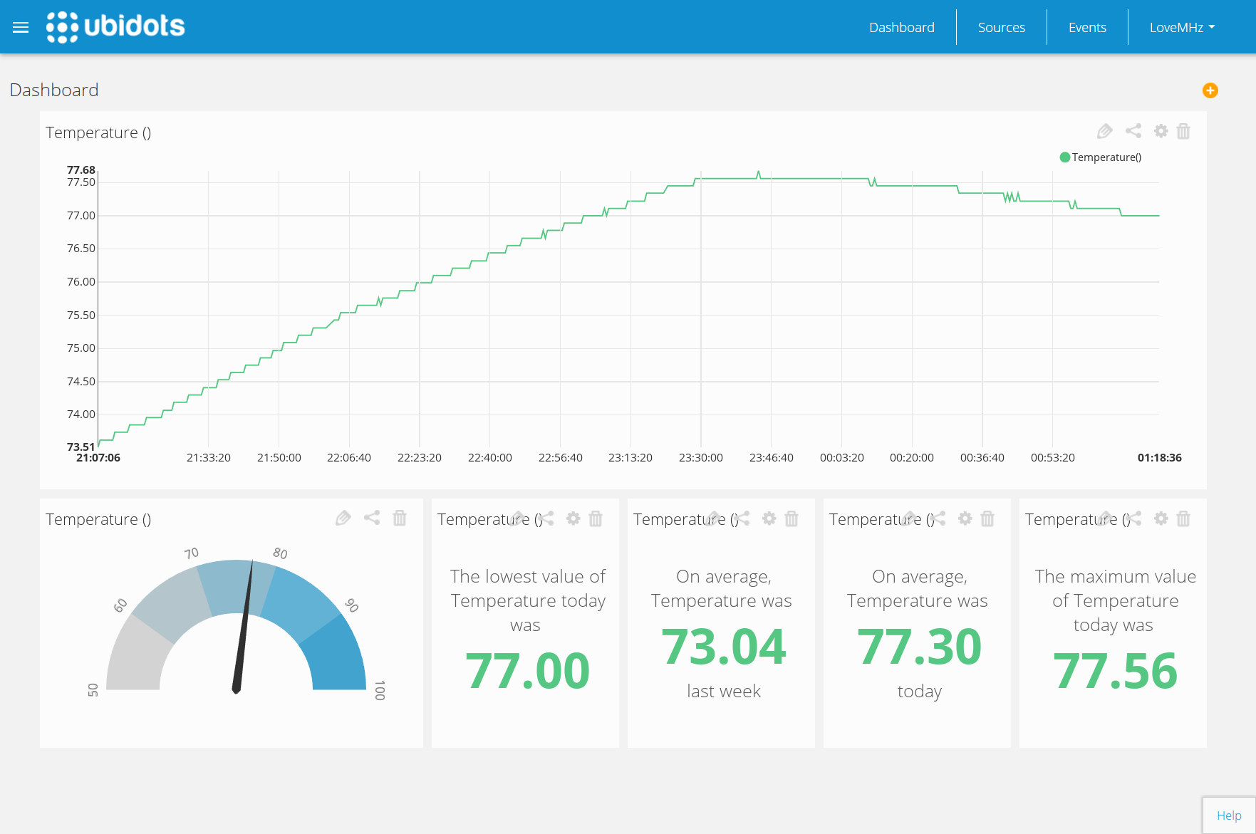
While there’s an increasingly large number of IoT implementation and tracking services being released everyday, I chose to go with the ubidots due to it’s easy to use REST API and free tier of 0.5 million sensor updates (dots) per month, with 1 month of historical storage. This allows me to track the water temperature at a conservative rate of every 30 seconds and view the resulting data for the month online from anywhere in the world.
Using this service solved one of my original concerns for this project on how to implement tracking, both efficiently and quickly. Luckily, by using ubidots, I went from a working prototype to having it fully implemented within an hour.
Conclusion
Now that I’m the NSA of fish metadata tracking, I can sit back and think over the project. This was a really fun project and I’m happy to say that I was able to accomplish the original goals I had set out to complete.
The ESP8266 has been a wonderful chip to work with and the community support, taking full advantage of it, has made it a breeze to use. This will most definitely not be the last project I take on using the ESP8266.
In the future, I hope to more closely evaluate using Node JS instead of C/C++ for the main code. Alongside implementing a proper REST API, I hope to also incorporate the MQTT protocol for a more complete IoT device.
Resources

 Come check out the source code to some of my projects. Or maybe you want to help out, report a bug, or poke around?
My Companies
 The future of retro begins here...
Join us on our adventure to repair, expand, and explore the realm of new possibilities.
The future of retro begins here...
Join us on our adventure to repair, expand, and explore the realm of new possibilities.
Subscribe
Subscribe to this blog via RSS.
Categories
Blog 31
Recent Posts
-
 Posted on 12 Jul 2025
-
Posted on 09 Jul 2025
-
Posted on 20 Jun 2025
-
Posted on 19 Mar 2016